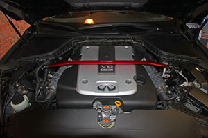
Instruction covers RWD and AWD Q50's. Will not work with hybrid
The following are instructions to replace the front sway bar on a Infiniti Q50 or Q50 AWD sedan. The sway bar in question, Tanabe Sustec, is listed for the Q50 RWD sedan but will fit the Q50 AWD as shown via this installation on a 2014 AWD.
Special Thanks goes out to Mike at www.TunerzStore.com for his personalized support of the project!
|
Parts Supplied By:
 |
|
|
Tools needed:12mm socket+ratchet, socket extention,17mm box wrench, 14mm box wrench, 8mm Allen wrench
|
|
|
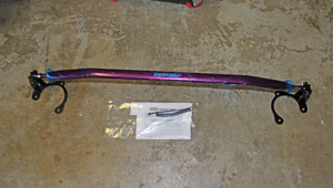 |
The Tanabe brace arrived well protected for shipping with a quality box. The strut bar was in a plastic package and all parts were neatly wrapped. The bar was protected and detailed instructions were provided. A wire wrap + zip tie were included but not needed.
For this installation I removed the mounting plates from the bar for installation. Per the pictures you will see that I left the rod bolts attached to the mounts. I suggest you simply remove the hex/14mm bolt from the mounts instead, thus, leaving the rod bolts attached to the rod.
NOTE: perform this installation on level ground. |
|
|
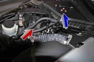 |
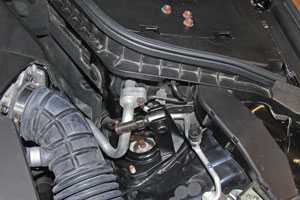
Step 1. I started on the passenger side and ran into a slight snag. The Q50 has two electrical lines and a metal pipe running over the section where the Strut Tower Bracket is supposed to mount and they are tied to the car. To make things easier I popped the top line free where it is mounted to the chassis. I then removed the three strut tower bolts with the 12mm socket.
|
|
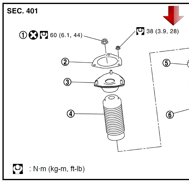 |
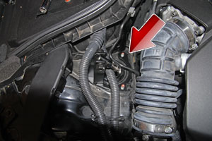
Step 2. Slide the bracket between the two electrical lines and twist it under the metal tube as shown in the image to the left. Once in place reinstall the 12mm nuts onto the strut tower. Torque to 28ft-lb per Q50 FSM (Tanabe doc states 22N*m which is only 16.22ft-lb).
|
|
 |
Step 3. The drivers side allows for easier access but there is another metal tube in the way. I still had no problem getting the brace mounts installed over the bolts. Once in place reinstall the 12mm nuts onto the strut tower. Torque to 28ft-lb per Q50 FSM.
|
|
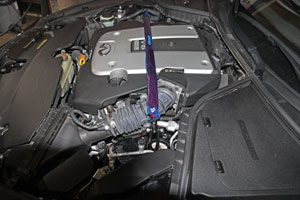 |
Step 4. Time to attach the bar. Lay the bar over the engine cover and twist both ends so they mate up with the holes of each mount. There should be a similar distance on each end of the bar (Somewhere around 4-5 threads). My preference is to get the bar to be an exact fit to the vehicle in its current state of rest. If the holes do not mate up then adjust each side until you have equal lengths and they fit. Attach each end to the mounting bracket using the supplied allen-head bolt w/lock washer and 14mm nut. The bolts should go in with the allen-head towards the front of the car for easy access. There should be a lock washer for the nut side. Insall bolts for both sides at this time. and finger tighten.
|
|
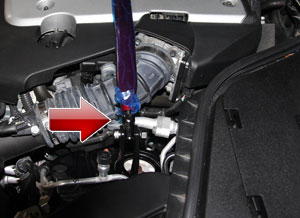 |
Step 5. Adjust the 17mm nut (red arrow) to be finger-tight against the bar. At this point close the hood to ensure you have proper clearance. Using my technique I had no issues, but, if there are problems Tanabe states that making the bar shorter, via the end links, will lower the height. Experiment for best fitment. When done, tighten the 17mm bolt on each end of the bar. Using the 8mm hex wrench and a 14mm box wrench proceed to tighten the bracket bolt. |
|
Time and Difficulty. Total time for installing the bar was 30 minutes as I was being extra careful and taking pictures. This could be done in 15 minutes. On a scale of 1 to 5, the installation is simple and requires common hand tools so I would give this a 1.5 (easy).
|
|
Disclaimer: The author will not be held responsible nor held liable for any damages due to these instructions. Anyone following these directions are doing so at their own risk. This Documentation may not be distributed without the authors consent.
|


