Other Sites of Interest


R2C MaxxFlow Cold Air Intake System Installation
| |||
|
Tools needed:Medium and small flat-head screw drivers, ratchet with 7mm | 8mm | 10mm sockets, 3mm and 4mm Allen wrench, pliers |
|||
|
|
|||
R2C intakes are what I would personally call a mid-ram intake. They are not true CAI's (Cold Air Intake) as they are located within the top of the engine bac, but, they do take advantage of somewhat direct airflow based upon their mounting location. This is the second R2C I have installed on personal cars and really enjoy their product and quality. |
|||
|
|
|||
;) Click for larger |
Parts. R2C intake packaging was top notch with all parts wrapped in bubble wrap. The system comes with new intake pipes, heat shields, filters (Black Hex filters in this case), two couplers, 6 large and 2 small clamps, two brackets, and all the bolts you will need for installation. Compared to some parts I have installed the instruction guide is very straight forward and relatively detailed. Installation was quite easy.
Note: My installation steps vary somewhat from the steps covered in the R2C installation guide. The order of both should work fine. |
;) Click for larger |
Step 1. Remove the 8 plastic retainers (clips, pop clips, rivet fasteners, whatever the various names are) from the front engine cover (AKA: Air duct (inlet)) as shown to the left. I utilize a small flat-head screwdriver to pry the center fastener up (gently) and then remove and put to the side. The front cover can then be removed and set to the side. |
;) Click for larger |
Step 2. Using the ratchet and 10mm socket remove the 2 front nuts and 3 bolts from the engine cover. When complete remove the engine cover and set to the side. |
;) Click for larger ;) Click for larger ;) Click for larger |
Step 3. To remove the intake system I have detailed the components to the left. From the top image, completely loosen the intake clamp (use either screwdriver or 8mm socket) at the throttle body with the medium screw driver. Using Pliers remove the hose clip (yellow arrow).
Second image: Remove the MAF sensor connector (red arrow) and unclip the wiring from the factory airbox (yellow arrow). Optionally here you can completely loosen the clamp holding the flex-intake tube to the Air Cleaner cover. Third image: Remove the 10mm bolt holding the Air Cleaner body to the chassis. From here you can remove the factory intake. I would start at the throttle body section as that gave me the most initial difficulty as the intake piping seemed stuck to the throttle body itself; this was resolved by running the small flat-head screw driver between the hose and the TB and using some wiggle action. The Air Cleaner body and Air Cleaner cover can simply be pulled up vertically and the whole intake can be removed from the car. Optionally you can remove the Air Cleaner body/cover first if it's easier that way, assuming you loosened the second hose clamp. Set all components to the side. At this point I reinstalled the 10mm bolt that held the factory Air Cleaner body to the chassis so it would not be lost. |
;) Click for larger |
Step 4. Install the coupler onto the throttle body, add a large clamp, thighten the clamp.
|
;) Click for larger ;) Click for larger |
Step 5. Attach the new intake pipe to the supplied heat shield. The crankcase tubes on the pipe should point the same direction as the angled side of the heat shield. The intake pipe also needs to be installed where the MAF sensor mounting location is on the top (see image in step 6 below).
Attaching the shield requires four supplied bolts, 8 washers, 4 lock washers, and 4 nuts. As shown via the picture on the left the bolts go through the heat shield and the nuts are attached from the pipe side. The order is: Bolt | washer | heat shield | pipe | washer | lock washer | nut. When all four are installed on each then tighten. I used a 8mm hex key with 8mm socket. See the first image to the left. |
;) Click for larger ;) Click for larger |
Step 6. In this step you move the MAF sensor from the old Air Cleaner cover to the new intake pipe. Use a 7mm socket to remove the bolts holding the sensor to the factory cover. Remove the sensor noting which end is facing front and back. Install the sensor onto the new pipe in the same direction as the old. Use the supplied bolts, there should be 2 that were included in the kit and are in their own bag. While the R2C documentation notes a 5/32 hex key I found a 7mm worked.
Note: Be careful with the MAF sensor and do not touch anything other than the connector section or you are looking for trouble. The second image shows the MAF sensor installed on the pipe and also shows the correlation of the heat shield to the crankcase piping referenced in the step above. The image represents the drivers-side intake, passenger side would be opposite. |
;) Click for larger ;) Click for larger |
Step 7. Install the full intake. (red arrows) I started by angling the pipe end into the coupler at the MAF. Make sure you have a large clamp installed first (although you can completely unscrew them regardless). I then attached the crankcase pipe utilizing the factory fitting instead of the R2C supplied clamp (up to you which one to use). Do not tighten the large clamp at the throttle body yet.
(yellow arrows) Reconnect the MAF sensor. If the MAF sensor cable does not connect the same as it did to the original system (has to be twisted 180 degrees to snap in) then you may have the MAF installed backward which will need to be fixed. When connected, reattach the cable clip to the hole in the heat shield as shown. |
Click for larger |
Step 8. To install the bracket you will need one of the supplied bolts with a lock washer and a washer. The bracket mounting location itself is under the angled trim section. Carefully pull up on the trim section (it should pull up a good 6" with no real trouble) and you will see a factory mounting location as pictured via the red arrow in the image to the left. Connect the bracket with the bolt. Before tightening the bolt I made sure the heat shield was not rubbing any of the bright silver metal hose that was directly under and to the inside of the shield (you can see it in the image from step 9). At that point you can tighten the bolt with the 8mm hex wrench, tighten the bolt where the bracket attaches to the heat shield and you can tighten the large clamp at the MAF. Adjust the crankcase hose as needed. Make sure the trim panel is back in place as well. |
;) Click for larger |
Step 9. Install the cone filter with a supplied large clamp as shown. |
;) Click for larger |
Step 10. Passenger side installs the same as the driver's side. The only main difference is the factory flexible intake pipe has a baffle which mounts to the intake as shown via the red arrow. Remove the 10mm bolt and remove this baffle with the factory pipe. Reinstall the 10mm bolt so it does not get lost. |
Time and Difficulty. Total time for installing the intakes was appx 1.5 hour as I was taking pictures and not in any rush. On a scale of 1-5 I would rate this install a 2.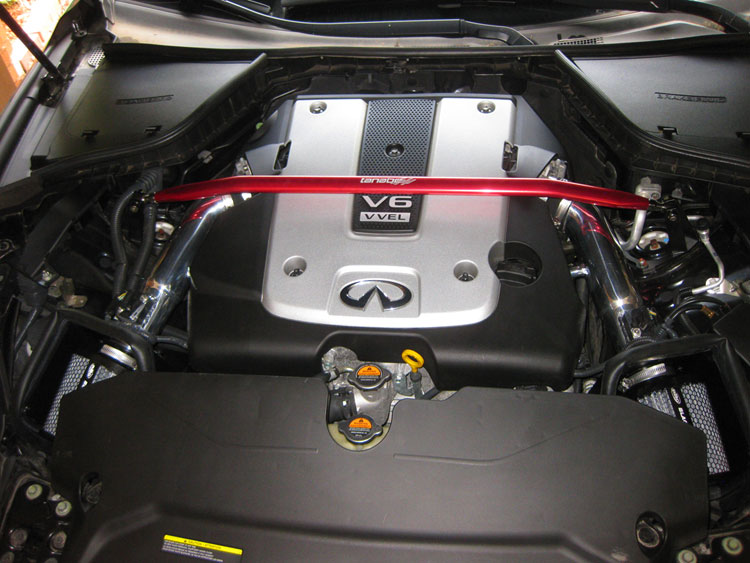 |
|
Disclaimer: The author will not be held responsible nor held liable for any damages due to these instructions. Anyone following these directions are doing so at their own risk. This Documentation may not be distributed without the authors consent. | |